一、TIM定时中断
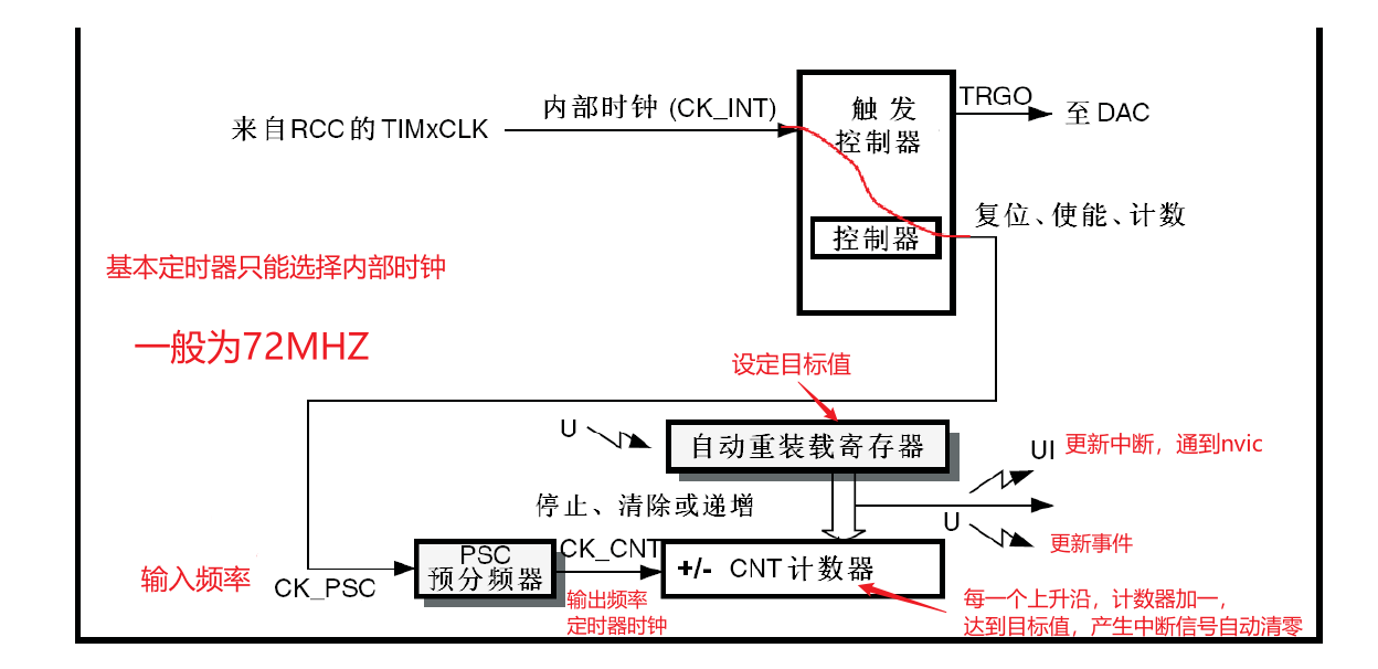
定时器可以对输入的时钟进行计数,并在计数值达到设定值时触发中断
例:stm32中定时器的基准时钟一般是72MHZ,【周期是频率的倒数1T = 1/72us】,如果计数72个,就是1us,计数72000个,就是1ms
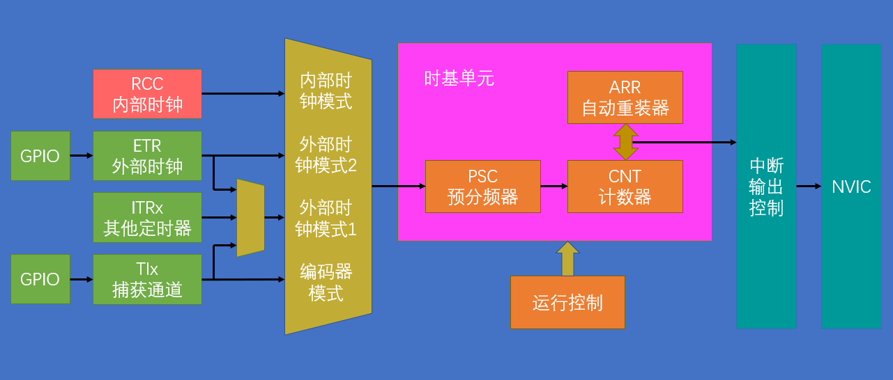
16位计数器、预分频器、自动重装寄存器的时基单元,在72MHz计数时钟下可以实现最大59.65s的定时
计数器:进行计数的寄存器,每来一个时钟,计数器加一
预分频器:对计数器时钟进行分频
自动重装寄存器:计数器的目标值,设定计多少数申请中断
2^16^=65536 预分频器和自动重装寄存器设置最大,定时器时间最大为59.65s【1/(72MHZ/65536*65536)】
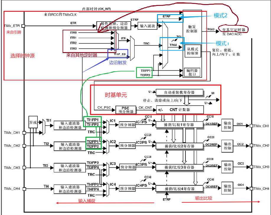
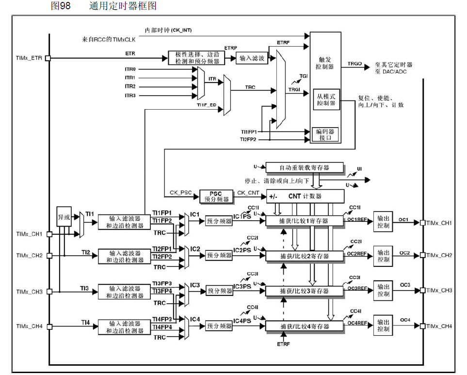
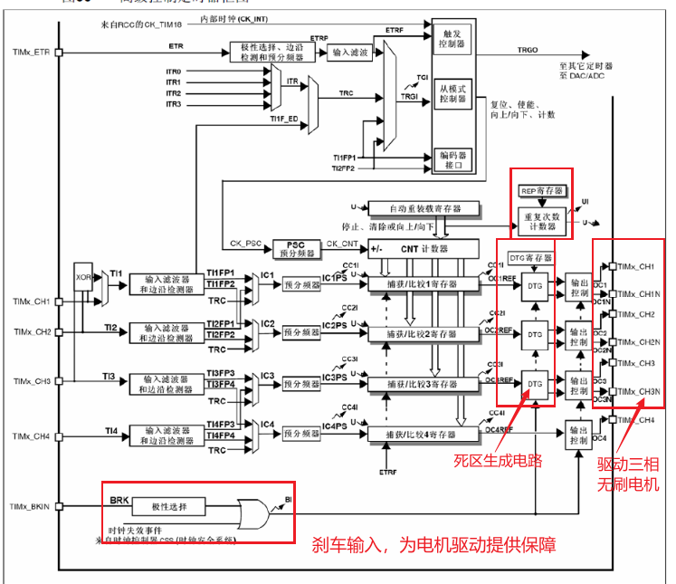
不仅具备基本的定时中断功能,而且还包含内外时钟源选择、输入捕获、输出比较、编码器接口、主从触发模式等多种功能
根据复杂度和应用场景分为了高级定时器、通用定时器、基本定时器三种类型
二、定时器类型
| 类型 |
编号 |
总线 |
功能 |
| 高级定时器 |
TIM1、TIM8 |
APB2 |
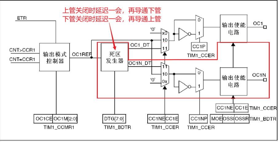
拥有通用定时器全部功能,并额外具有重复计数器、死区生成、互补输出、刹车输入等功能 |
| 通用定时器 |
TIM2、TIM3、TIM4、TIM5 |
APB1 |
拥有基本定时器全部功能,并额外具有内外时钟源选择、输入捕获、输出比较、编码器接口、主从触发模式等功能 |
| 基本定时器 |
TIM6、TIM7 |
APB1 |
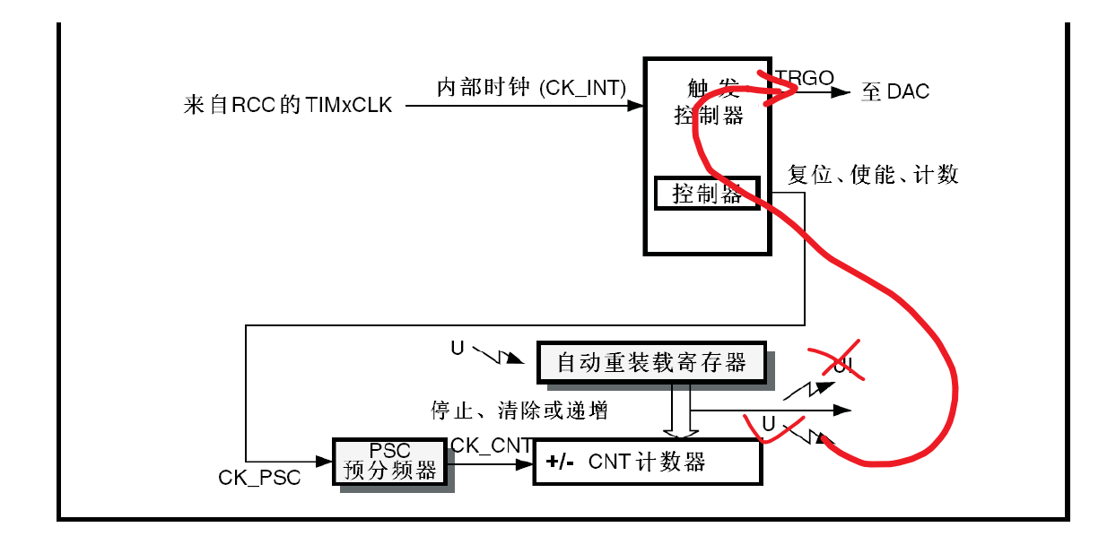
拥有定时中断、主模式触发DAC的功能 |
STM32F103C8T6定时器资源:TIM1、TIM2、TIM3、TIM4
2.1基本定时器
TIM6和TIM7定时器的主要功能包括:

2.1.1分频的作用
便于计算,计时更加精确
-
以12MHZ为例:
-
不分频
一个时钟周期为 T = 1/12 us,如果我们需要1us,需要12T,这个很好理解吧,但是我们使用的时候经常是要以秒(s)微秒(ms)进行计时的,当我们需要1ms的时候,我们就需要计数12000T,这个数是已经很大了
-
12分频
12分频后,12MHZ变为1MHZ,一个时钟周期为 T = 1/1 us = 1us,如果我们需要1us,需要1T;需要1ms时,只需要1000T
我们很清楚的看到分频以后,计一次数就是1us,这不但利用我们去计算定时时间,而且计算的次数明显减少了,那么为什么说计数次数减少就可以提高精度呢?可以想一下平时使用的钟表,当我们使用的时间长了,表就会不太准,时钟也是一样,我们计数次数多了,难免会产生误差,一次两次小误差肯能影响不大,但是成千上百次误差的影响那可就大了
定时时间更长
-
以72MHZ为例
-
不分频
一个时钟周期为 T = 1/72 us,16位定时器的范围是0~65535,那么一个范围计数完成的时间大概是0.94ms
-
3分频
3分频后,72MHZ变为24MHZ,一个时钟周期为 T = 1/24 us ,那么一个范围计数完成的时间大概是2.73ms
-
72分频
72MHZ变为1MHZ,一个时钟周期为 T =1 us ,那么一个范围计数完成的时间大概是65.5ms
由于分频以后,到达同一个计数时间的计数次数减少,所以在16位的定时器范围内,定时器的定时时间最大值增加【定时器计数最大值是不可改变的,2^16^,所以我们只能改变频率来改变计数最大时间】
2.1.2预分频器
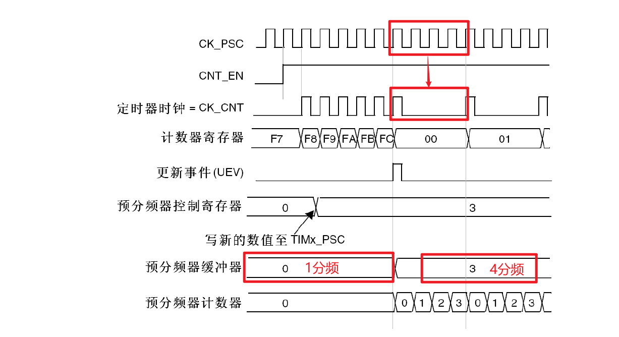
预分频可以以系数介于1至65536之间的任意数值对计数器时钟分频。它是通过一个16位寄存器(TIMx_PSC)的计数实现分频。因为TIMx_PSC控制寄存器具有缓冲,可以在运行过程中改变它的数值,新的预分频数值将在下一个更新事件时起作用
实际分频数 = 分频器的值 + 1
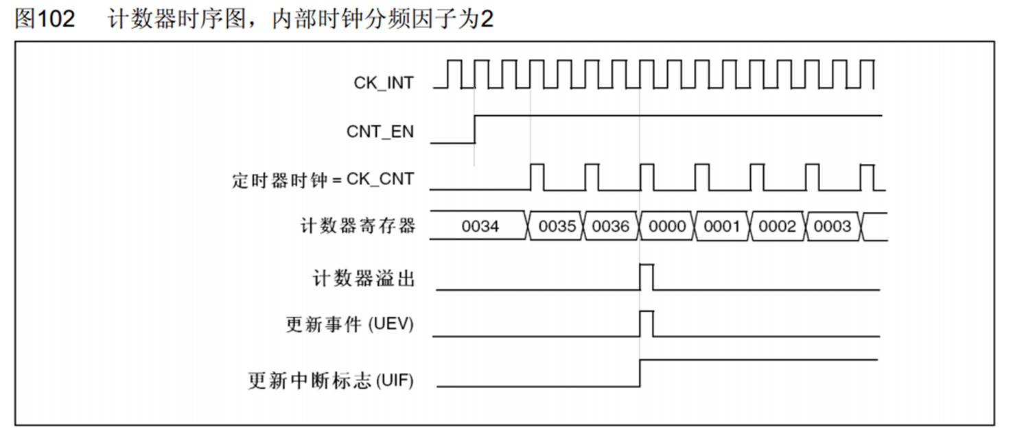
计数器计数频率:CK_CNT = CK_PSC / (PSC + 1)

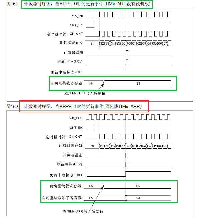
缓冲器(也叫作影子寄存器),是实际起作用的寄存器。比如:在计数过程中突然改变分频系数,那么一个周期前半部分和后半部分的频率就会不一致,这可能会产生一些不好的影响。但是加上缓冲器后,改变分频系数并不会立即改变这一个周期的频率,它会等到这个周期结束后,产生更新事件,才会去改变,这样就保证了stm32的严谨性
2.1.3计数模式

计数器溢出频率:CK_CNT_OV = CK_CNT / (ARR + 1) = CK_PSC / (PSC + 1) / (ARR + 1)
计数器使用影子寄存器 和 计数器不使用影子寄存器

2.1.4主模式触发DAC功能
当我们使用DAC时,需要每隔一段时间都要输出一段波形,按正常思路来说,我们要使用中断,每隔一段时间调用一次中断里面的代码,实现DAC转换。但是频繁调用中断会影响到主程序的进行,阻碍其他中断的进行
如果我们使用主模式的话,就可以把定时器的更新事件映射到触发输出TRGO,然后将TRGO接到DAC触发转换引脚上,这样就不需要更新中断来实现DAC转换了。整个过程不需要软件的参与,实现了硬件的自动化

2.2通用定时器
通用TIMx (TIM2、TIM3、TIM4和TIM5)定时器功能包括:


2.2.1计数模式
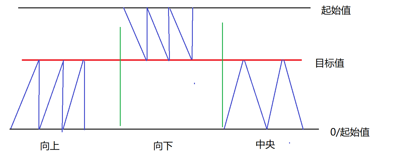
向上计数模式、向下计数模式、中央对齐模式(向上/向下计数)

向上计数模式:每次+1,加到目标值,申请中断,归零
向下计数模式:每次-1,减到目标值,申请中断,归起始值
中央对齐模式(向上/向下计数):每次+1,加到目标值,申请中断;之后每次-1,减到起始值,申请中断
2.3高级定时器

三、定时中断基本结构

使用中断输出控制的原因:
定时器模块中很多地方都要申请中断,定时器图中的向上折的箭头都表示要申请中断,所以需要控制这些中断,如果需要就允许,不需要就不允许
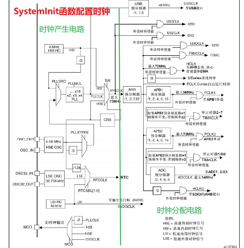
时钟树

如果不改变SystemInit里面的配置,三种定时器中内部基准时钟均为72MHZ
实例一、定时中断和内外部时钟代码实现
1.1、定时中断
**功能实现:**每隔1S计数一次
**注意:**需要手动清除中断初始化时产生的中断标记,不然默认其实值为1,而不是0
timer.c
1
2
3
4
5
6
7
8
9
10
11
12
13
14
15
16
17
18
19
20
21
22
23
24
25
26
27
28
29
30
31
32
33
34
35
36
37
38
39
40
41
42
43
44
45
46
47
48
| #include "stm32f10x.h"
void Timer_Init(void){
RCC_APB1PeriphClockCmd(RCC_APB1Periph_TIM2,ENABLE);
TIM_InternalClockConfig(TIM2);
TIM_TimeBaseInitTypeDef TIM_TimeBaseInitStructure;
TIM_TimeBaseInitStructure.TIM_ClockDivision = TIM_CKD_DIV1;
TIM_TimeBaseInitStructure.TIM_CounterMode = TIM_CounterMode_Up;
TIM_TimeBaseInitStructure.TIM_Period = 10000 - 1;
TIM_TimeBaseInitStructure.TIM_Prescaler = 7200 - 1;
TIM_TimeBaseInitStructure.TIM_RepetitionCounter = 0;
TIM_TimeBaseInit(TIM2,&TIM_TimeBaseInitStructure);
TIM_ClearFlag(TIM2,TIM_IT_Update);
TIM_ITConfig(TIM2,TIM_IT_Update,ENABLE);
NVIC_PriorityGroupConfig(NVIC_PriorityGroup_2);
NVIC_InitTypeDef NVIC_InitStructure;
NVIC_InitStructure.NVIC_IRQChannel = TIM2_IRQn;
NVIC_InitStructure.NVIC_IRQChannelCmd = ENABLE;
NVIC_InitStructure.NVIC_IRQChannelPreemptionPriority = 2;
NVIC_InitStructure.NVIC_IRQChannelSubPriority = 1;
NVIC_Init(&NVIC_InitStructure);
TIM_Cmd(TIM2,ENABLE);
}
|
timer.h
1
2
3
4
5
6
7
| #ifndef __TIMER_H__
#define __TIMER_H__
void Timer_Init(void);
#endif
|
main.c
1
2
3
4
5
6
7
8
9
10
11
12
13
14
15
16
17
18
19
20
21
22
23
24
25
| #include "stm32f10x.h"
#include "OLED.h"
#include "Timer.h"
uint16_t num = 0;
int main(){
OLED_Init();
Timer_Init();
OLED_ShowString(1,1,"Num:");
while(1){
OLED_ShowNum(1,5,num,5);
}
}
void TIM2_IRQHandler(void){
if(TIM_GetITStatus(TIM2,TIM_IT_Update) == SET){
num++;
TIM_ClearITPendingBit(TIM2,TIM_IT_Update);
}
}
|
OLED.c
1
2
3
4
5
6
7
8
9
10
11
12
13
14
15
16
17
18
19
20
21
22
23
24
25
26
27
28
29
30
31
32
33
34
35
36
37
38
39
40
41
42
43
44
45
46
47
48
49
50
51
52
53
54
55
56
57
58
59
60
61
62
63
64
65
66
67
68
69
70
71
72
73
74
75
76
77
78
79
80
81
82
83
84
85
86
87
88
89
90
91
92
93
94
95
96
97
98
99
100
101
102
103
104
105
106
107
108
109
110
111
112
113
114
115
116
117
118
119
120
121
122
123
124
125
126
127
128
129
130
131
132
133
134
135
136
137
138
139
140
141
142
143
144
145
146
147
148
149
150
151
152
153
154
155
156
157
158
159
160
161
162
163
164
165
166
167
168
169
170
171
172
173
174
175
176
177
178
179
180
181
182
183
184
185
186
187
188
189
190
191
192
193
194
195
196
197
198
199
200
201
202
203
204
205
206
207
208
209
210
211
212
213
214
215
216
217
218
219
220
221
222
223
224
225
226
227
228
229
230
231
232
233
234
235
236
237
238
239
240
241
242
243
244
245
246
247
248
249
250
251
252
253
254
255
256
257
258
259
260
261
262
263
264
265
266
267
268
269
270
271
272
273
274
275
276
277
278
279
280
281
282
283
284
285
286
287
288
289
290
291
292
293
294
295
296
297
298
299
300
301
302
303
304
305
306
307
308
309
310
311
312
313
314
315
316
317
318
319
320
321
322
| #include "stm32f10x.h"
#include "OLED_Font.h"
#define OLED_W_SCL(x) GPIO_WriteBit(GPIOB, GPIO_Pin_8, (BitAction)(x))
#define OLED_W_SDA(x) GPIO_WriteBit(GPIOB, GPIO_Pin_9, (BitAction)(x))
void OLED_I2C_Init(void)
{
RCC_APB2PeriphClockCmd(RCC_APB2Periph_GPIOB, ENABLE);
GPIO_InitTypeDef GPIO_InitStructure;
GPIO_InitStructure.GPIO_Mode = GPIO_Mode_Out_OD;
GPIO_InitStructure.GPIO_Speed = GPIO_Speed_50MHz;
GPIO_InitStructure.GPIO_Pin = GPIO_Pin_8;
GPIO_Init(GPIOB, &GPIO_InitStructure);
GPIO_InitStructure.GPIO_Pin = GPIO_Pin_9;
GPIO_Init(GPIOB, &GPIO_InitStructure);
OLED_W_SCL(1);
OLED_W_SDA(1);
}
void OLED_I2C_Start(void)
{
OLED_W_SDA(1);
OLED_W_SCL(1);
OLED_W_SDA(0);
OLED_W_SCL(0);
}
void OLED_I2C_Stop(void)
{
OLED_W_SDA(0);
OLED_W_SCL(1);
OLED_W_SDA(1);
}
void OLED_I2C_SendByte(uint8_t Byte)
{
uint8_t i;
for (i = 0; i < 8; i++)
{
OLED_W_SDA(Byte & (0x80 >> i));
OLED_W_SCL(1);
OLED_W_SCL(0);
}
OLED_W_SCL(1);
OLED_W_SCL(0);
}
void OLED_WriteCommand(uint8_t Command)
{
OLED_I2C_Start();
OLED_I2C_SendByte(0x78);
OLED_I2C_SendByte(0x00);
OLED_I2C_SendByte(Command);
OLED_I2C_Stop();
}
void OLED_WriteData(uint8_t Data)
{
OLED_I2C_Start();
OLED_I2C_SendByte(0x78);
OLED_I2C_SendByte(0x40);
OLED_I2C_SendByte(Data);
OLED_I2C_Stop();
}
void OLED_SetCursor(uint8_t Y, uint8_t X)
{
OLED_WriteCommand(0xB0 | Y);
OLED_WriteCommand(0x10 | ((X & 0xF0) >> 4));
OLED_WriteCommand(0x00 | (X & 0x0F));
}
void OLED_Clear(void)
{
uint8_t i, j;
for (j = 0; j < 8; j++)
{
OLED_SetCursor(j, 0);
for(i = 0; i < 128; i++)
{
OLED_WriteData(0x00);
}
}
}
void OLED_ShowChar(uint8_t Line, uint8_t Column, char Char)
{
uint8_t i;
OLED_SetCursor((Line - 1) * 2, (Column - 1) * 8);
for (i = 0; i < 8; i++)
{
OLED_WriteData(OLED_F8x16[Char - ' '][i]);
}
OLED_SetCursor((Line - 1) * 2 + 1, (Column - 1) * 8);
for (i = 0; i < 8; i++)
{
OLED_WriteData(OLED_F8x16[Char - ' '][i + 8]);
}
}
void OLED_ShowString(uint8_t Line, uint8_t Column, char *String)
{
uint8_t i;
for (i = 0; String[i] != '\0'; i++)
{
OLED_ShowChar(Line, Column + i, String[i]);
}
}
uint32_t OLED_Pow(uint32_t X, uint32_t Y)
{
uint32_t Result = 1;
while (Y--)
{
Result *= X;
}
return Result;
}
void OLED_ShowNum(uint8_t Line, uint8_t Column, uint32_t Number, uint8_t Length)
{
uint8_t i;
for (i = 0; i < Length; i++)
{
OLED_ShowChar(Line, Column + i, Number / OLED_Pow(10, Length - i - 1) % 10 + '0');
}
}
void OLED_ShowSignedNum(uint8_t Line, uint8_t Column, int32_t Number, uint8_t Length)
{
uint8_t i;
uint32_t Number1;
if (Number >= 0)
{
OLED_ShowChar(Line, Column, '+');
Number1 = Number;
}
else
{
OLED_ShowChar(Line, Column, '-');
Number1 = -Number;
}
for (i = 0; i < Length; i++)
{
OLED_ShowChar(Line, Column + i + 1, Number1 / OLED_Pow(10, Length - i - 1) % 10 + '0');
}
}
void OLED_ShowHexNum(uint8_t Line, uint8_t Column, uint32_t Number, uint8_t Length)
{
uint8_t i, SingleNumber;
for (i = 0; i < Length; i++)
{
SingleNumber = Number / OLED_Pow(16, Length - i - 1) % 16;
if (SingleNumber < 10)
{
OLED_ShowChar(Line, Column + i, SingleNumber + '0');
}
else
{
OLED_ShowChar(Line, Column + i, SingleNumber - 10 + 'A');
}
}
}
void OLED_ShowBinNum(uint8_t Line, uint8_t Column, uint32_t Number, uint8_t Length)
{
uint8_t i;
for (i = 0; i < Length; i++)
{
OLED_ShowChar(Line, Column + i, Number / OLED_Pow(2, Length - i - 1) % 2 + '0');
}
}
void OLED_Init(void)
{
uint32_t i, j;
for (i = 0; i < 1000; i++)
{
for (j = 0; j < 1000; j++);
}
OLED_I2C_Init();
OLED_WriteCommand(0xAE);
OLED_WriteCommand(0xD5);
OLED_WriteCommand(0x80);
OLED_WriteCommand(0xA8);
OLED_WriteCommand(0x3F);
OLED_WriteCommand(0xD3);
OLED_WriteCommand(0x00);
OLED_WriteCommand(0x40);
OLED_WriteCommand(0xA1);
OLED_WriteCommand(0xC8);
OLED_WriteCommand(0xDA);
OLED_WriteCommand(0x12);
OLED_WriteCommand(0x81);
OLED_WriteCommand(0xCF);
OLED_WriteCommand(0xD9);
OLED_WriteCommand(0xF1);
OLED_WriteCommand(0xDB);
OLED_WriteCommand(0x30);
OLED_WriteCommand(0xA4);
OLED_WriteCommand(0xA6);
OLED_WriteCommand(0x8D);
OLED_WriteCommand(0x14);
OLED_WriteCommand(0xAF);
OLED_Clear();
}
|
OLED.h
1
2
3
4
5
6
7
8
9
10
11
12
13
14
| #ifndef __OLED_H
#define __OLED_H
void OLED_Init(void);
void OLED_Clear(void);
void OLED_ShowChar(uint8_t Line, uint8_t Column, char Char);
void OLED_ShowString(uint8_t Line, uint8_t Column, char *String);
void OLED_ShowNum(uint8_t Line, uint8_t Column, uint32_t Number, uint8_t Length);
void OLED_ShowSignedNum(uint8_t Line, uint8_t Column, int32_t Number, uint8_t Length);
void OLED_ShowHexNum(uint8_t Line, uint8_t Column, uint32_t Number, uint8_t Length);
void OLED_ShowBinNum(uint8_t Line, uint8_t Column, uint32_t Number, uint8_t Length);
#endif
|
1.2、外部时钟
**功能实现:**每遮挡一次计数器+1
**注意:**如果出现遮挡一次跳跃好多次,需要添加滤波
timer.c
1
2
3
4
5
6
7
8
9
10
11
12
13
14
15
16
17
18
19
20
21
22
23
24
25
26
27
28
29
30
31
32
33
34
35
36
37
38
39
40
41
42
43
44
45
46
47
48
49
50
51
52
53
54
55
56
57
58
59
60
61
| #include "stm32f10x.h"
void Timer_Init(void){
RCC_APB1PeriphClockCmd(RCC_APB1Periph_TIM2,ENABLE);
RCC_APB2PeriphClockCmd(RCC_APB2Periph_GPIOA,ENABLE);
GPIO_InitTypeDef GPIO_InitStructure;
GPIO_InitStructure.GPIO_Mode = GPIO_Mode_IPU;
GPIO_InitStructure.GPIO_Pin = GPIO_Pin_0;
GPIO_InitStructure.GPIO_Speed = GPIO_Speed_50MHz;
GPIO_Init(GPIOA,&GPIO_InitStructure);
TIM_ETRClockMode2Config(TIM2,TIM_ExtTRGPSC_OFF,TIM_ExtTRGPolarity_NonInverted,0x0f);
TIM_TimeBaseInitTypeDef TIM_TimeBaseInitStructure;
TIM_TimeBaseInitStructure.TIM_ClockDivision = TIM_CKD_DIV1;
TIM_TimeBaseInitStructure.TIM_CounterMode = TIM_CounterMode_Up;
TIM_TimeBaseInitStructure.TIM_Period = 10 - 1;
TIM_TimeBaseInitStructure.TIM_Prescaler = 1 - 1;
TIM_TimeBaseInitStructure.TIM_RepetitionCounter = 0;
TIM_TimeBaseInit(TIM2,&TIM_TimeBaseInitStructure);
TIM_ClearFlag(TIM2,TIM_IT_Update);
TIM_ITConfig(TIM2,TIM_IT_Update,ENABLE);
NVIC_PriorityGroupConfig(NVIC_PriorityGroup_2);
NVIC_InitTypeDef NVIC_InitStructure;
NVIC_InitStructure.NVIC_IRQChannel = TIM2_IRQn;
NVIC_InitStructure.NVIC_IRQChannelCmd = ENABLE;
NVIC_InitStructure.NVIC_IRQChannelPreemptionPriority = 2;
NVIC_InitStructure.NVIC_IRQChannelSubPriority = 1;
NVIC_Init(&NVIC_InitStructure);
TIM_Cmd(TIM2,ENABLE);
}
uint16_t Timer_GetCount(void){
return TIM_GetCounter(TIM2);
}
|
timer.h
1
2
3
4
5
6
7
8
| #ifndef __TIMER_H__
#define __TIMER_H__
void Timer_Init(void);
uint16_t Timer_GetCount(void);
#endif
|
main.c
1
2
3
4
5
6
7
8
9
10
11
12
13
14
15
16
17
18
19
20
21
22
23
24
25
26
| #include "stm32f10x.h"
#include "OLED.h"
#include "Timer.h"
uint16_t num = 0;
int main(){
OLED_Init();
Timer_Init();
OLED_ShowString(1,1,"Num:");
OLED_ShowString(2,1,"CNT:");
while(1){
OLED_ShowNum(1,5,num,5);
OLED_ShowNum(2,5,Timer_GetCount(),5);
}
}
void TIM2_IRQHandler(void){
if(TIM_GetITStatus(TIM2,TIM_IT_Update) == SET){
num++;
TIM_ClearITPendingBit(TIM2,TIM_IT_Update);
}
}
|
四、TIM输出比较
OC(Output Compare)输出比较
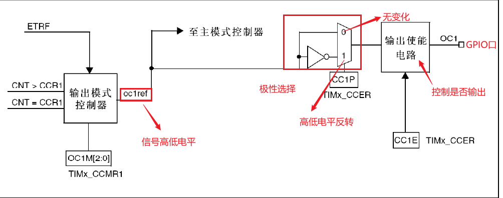
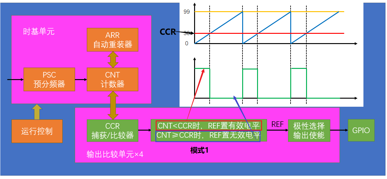
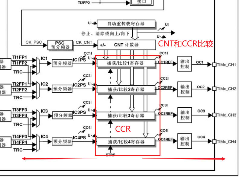
输出比较可以通过比较CNT与CCR寄存器值的关系,来对输出电平进行置1、置0或翻转的操作,用于输出一定频率和占空比的PWM波形
CCR是输出比较寄存器

每个高级定时器和通用定时器都拥有4个输出比较通道
高级定时器的前3个通道额外拥有死区生成和互补输出的功能
4.1、PWM简介
PWM(Pulse Width Modulation)脉冲宽度调制
在具有惯性的系统中,可以通过对一系列脉冲的宽度进行调制,来等效地获得所需要的模拟参量,常应用于电机控速等领域
PWM参数:频率 = 1 / TS **占空比 **= TON / TS 分辨率 = 占空比变化步距
占空比越大,模拟出的电压越趋近于高电平,占空比越小,模拟出的电压越趋近于低电平

4.2、输出比较通道
4.2.1输出比较通道(通用定时器)

4.2.2输出比较通道(高级定时器)

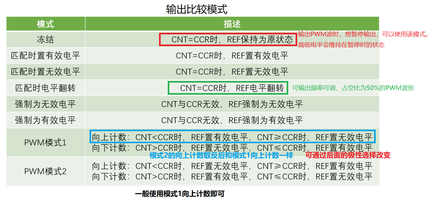
4.3 输出比较模式

4.4PWM基本结构

PWM频率: Freq = { CK_PSC / (PSC + 1) } / (ARR + 1)
PWM的频率=计数器更新频率
PWM占空比: Duty = CCR / (ARR + 1)
PWM分辨率: Reso = 1 / (ARR + 1)
分辨率定义为占空比最小的变化步距,占空比变化的越细腻越好
五、舵机
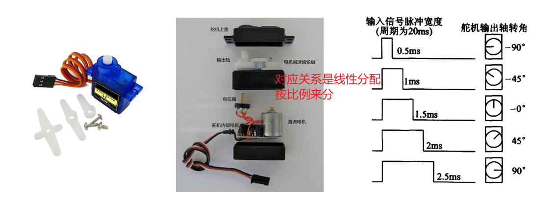
舵机是一种根据输入PWM信号占空比来控制输出角度的装置
输入PWM信号要求:周期为20ms,高电平宽度为0.5ms~2.5ms

在这里,PWM当做通讯协议使用,不是PWM等效一个模拟输出

六、直流电机
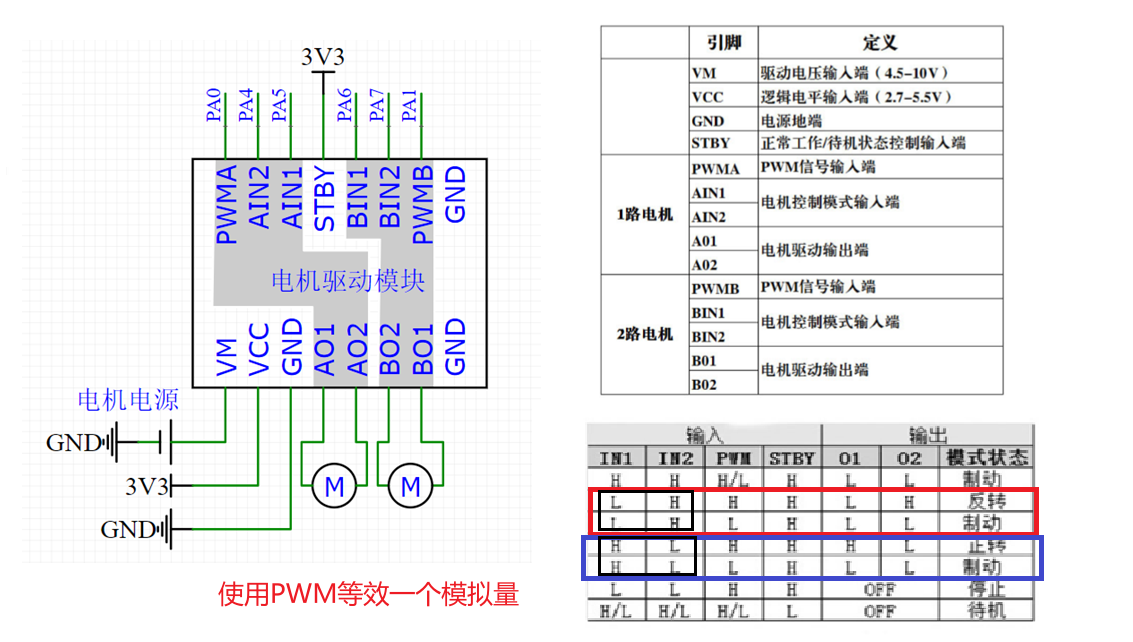
直流电机是一种将电能转换为机械能的装置,有两个电极,当电极正接时,电机正转,当电极反接时,电机反转
直流电机属于大功率器件,GPIO口无法直接驱动,需要配合电机驱动电路来操作
TB6612是一款双路H桥型的直流电机驱动芯片,可以驱动两个直流电机并且控制其转速和方向


实例二、PWM驱动呼吸灯&舵机&直流电机代码实现
2.1、PWM驱动LED呼吸灯
**功能实现:**LED实现呼吸效果
**注意:**这里用过改变CCR的值来改变占空,比达到呼吸效果;但是占空比的值是有CCR和ARR+1共同决定的
PWM.c
1
2
3
4
5
6
7
8
9
10
11
12
13
14
15
16
17
18
19
20
21
22
23
24
25
26
27
28
29
30
31
32
33
34
35
36
37
38
39
40
41
42
43
44
45
46
47
48
| #include "stm32f10x.h"
void PWM_Init(void){
RCC_APB1PeriphClockCmd(RCC_APB1Periph_TIM2,ENABLE);
RCC_APB2PeriphClockCmd(RCC_APB2Periph_GPIOA,ENABLE);
GPIO_InitTypeDef GPIO_InitStructure;
GPIO_InitStructure.GPIO_Mode = GPIO_Mode_AF_PP;
GPIO_InitStructure.GPIO_Pin = GPIO_Pin_0;
GPIO_InitStructure.GPIO_Speed = GPIO_Speed_50MHz;
GPIO_Init(GPIOA,&GPIO_InitStructure);
TIM_InternalClockConfig(TIM2);
TIM_TimeBaseInitTypeDef TIM_TimeBaseInitStructure;
TIM_TimeBaseInitStructure.TIM_ClockDivision = TIM_CKD_DIV1;
TIM_TimeBaseInitStructure.TIM_CounterMode = TIM_CounterMode_Up;
TIM_TimeBaseInitStructure.TIM_Period = 100 - 1;
TIM_TimeBaseInitStructure.TIM_Prescaler = 720 - 1;
TIM_TimeBaseInitStructure.TIM_RepetitionCounter = 0;
TIM_TimeBaseInit(TIM2,&TIM_TimeBaseInitStructure);
TIM_OCInitTypeDef TIM_OCInitStructure;
TIM_OCStructInit(&TIM_OCInitStructure);
TIM_OCInitStructure.TIM_OCMode = TIM_OCMode_PWM1;
TIM_OCInitStructure.TIM_OCPolarity = TIM_OCPolarity_High;
TIM_OCInitStructure.TIM_OutputState = TIM_OutputState_Enable;
TIM_OCInitStructure.TIM_Pulse = 0;
TIM_OC1Init(TIM2, &TIM_OCInitStructure);
TIM_Cmd(TIM2,ENABLE);
}
void PWM_SetCompare1(uint16_t Compare)
{
TIM_SetCompare1(TIM2, Compare);
}
|
PWM.h
1
2
3
4
5
6
7
8
| #ifndef __PWM_H__
#define __PWM_H__
void PWM_Init(void);
void PWM_SetCompare1(uint16_t Compare);
#endif
|
main.c
1
2
3
4
5
6
7
8
9
10
11
12
13
14
15
16
17
18
19
20
21
22
| #include "stm32f10x.h"
#include "Delay.h"
#include "PWM.h"
#include "OLED.h"
uint8_t i;
int main(){
OLED_Init();
PWM_Init();
while(1){
for(i = 0; i< 100; i++){
PWM_SetCompare1(i);
Delay_ms(10);
}
for(i = 0; i< 100; i++){
PWM_SetCompare1(100-i);
Delay_ms(10);
}
}
}
|
Delay.c
1
2
3
4
5
6
7
8
9
10
11
12
13
14
15
16
17
18
19
20
21
22
23
24
25
26
27
28
29
30
31
32
33
34
35
36
37
38
39
40
41
42
| #include "stm32f10x.h"
void Delay_us(uint32_t xus)
{
SysTick->LOAD = 72 * xus;
SysTick->VAL = 0x00;
SysTick->CTRL = 0x00000005;
while(!(SysTick->CTRL & 0x00010000));
SysTick->CTRL = 0x00000004;
}
void Delay_ms(uint32_t xms)
{
while(xms--)
{
Delay_us(1000);
}
}
void Delay_s(uint32_t xs)
{
while(xs--)
{
Delay_ms(1000);
}
}
|
Delay.h
1
2
3
4
5
6
7
8
9
| #ifndef __DELAY_H
#define __DELAY_H
void Delay_us(uint32_t us);
void Delay_ms(uint32_t ms);
void Delay_s(uint32_t s);
#endif
|
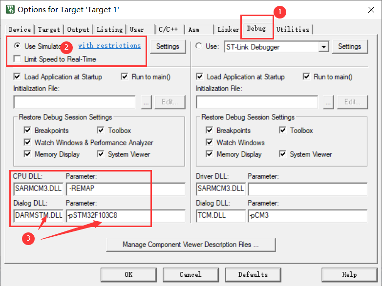
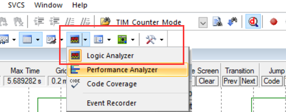
拓展:keil5自带示波器使用
1.点击魔术棒

2.进入Debug
先设置为Use Simulator,然后去设置Dialog DLL和其后面的Parameter.
其中将Dialog DLL设置为:DARMSTM.DLL
Parameter设置为-p单片机型号

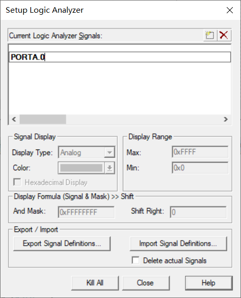
3.进入调试模式,调出示波器

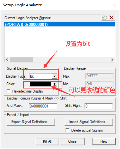
4.点击Setup设置仿真端口
在里面加入要查看的端口,格式为PORTX.Y【X为A,B,C…;Y为1,2,3,…】


5.查看仿真效果

2.2、PWM驱动舵机
**功能实现:**通过按键控制舵机旋转角度
PWM.c
1
2
3
4
5
6
7
8
9
10
11
12
13
14
15
16
17
18
19
20
21
22
23
24
25
26
27
28
29
30
31
32
33
34
35
36
37
38
39
40
41
42
43
44
45
46
47
48
| #include "stm32f10x.h"
void PWM_Init(void){
RCC_APB1PeriphClockCmd(RCC_APB1Periph_TIM2,ENABLE);
RCC_APB2PeriphClockCmd(RCC_APB2Periph_GPIOA,ENABLE);
GPIO_InitTypeDef GPIO_InitStructure;
GPIO_InitStructure.GPIO_Mode = GPIO_Mode_AF_PP;
GPIO_InitStructure.GPIO_Pin = GPIO_Pin_1;
GPIO_InitStructure.GPIO_Speed = GPIO_Speed_50MHz;
GPIO_Init(GPIOA,&GPIO_InitStructure);
TIM_InternalClockConfig(TIM2);
TIM_TimeBaseInitTypeDef TIM_TimeBaseInitStructure;
TIM_TimeBaseInitStructure.TIM_ClockDivision = TIM_CKD_DIV1;
TIM_TimeBaseInitStructure.TIM_CounterMode = TIM_CounterMode_Up;
TIM_TimeBaseInitStructure.TIM_Period = 20000 - 1;
TIM_TimeBaseInitStructure.TIM_Prescaler = 72 - 1;
TIM_TimeBaseInitStructure.TIM_RepetitionCounter = 0;
TIM_TimeBaseInit(TIM2,&TIM_TimeBaseInitStructure);
TIM_OCInitTypeDef TIM_OCInitStructure;
TIM_OCStructInit(&TIM_OCInitStructure);
TIM_OCInitStructure.TIM_OCMode = TIM_OCMode_PWM1;
TIM_OCInitStructure.TIM_OCPolarity = TIM_OCPolarity_High;
TIM_OCInitStructure.TIM_OutputState = TIM_OutputState_Enable;
TIM_OCInitStructure.TIM_Pulse = 0;
TIM_OC2Init(TIM2, &TIM_OCInitStructure);
TIM_Cmd(TIM2,ENABLE);
}
void PWM_SetCompare2(uint16_t Compare)
{
TIM_SetCompare2(TIM2, Compare);
}
|
PWM.h
1
2
3
4
5
6
7
8
| #ifndef __PWM_H__
#define __PWM_H__
void PWM_Init(void);
void PWM_SetCompare2(uint16_t Compare);
#endif
|
Servo.c
1
2
3
4
5
6
7
8
9
10
11
12
13
| #include "stm32f10x.h"
#include "PWM.h"
void Servo_Init(void)
{
PWM_Init();
}
void Servo_SetAngle(float Angle)
{
PWM_SetCompare2(Angle / 180 * 2000 + 500);
}
|
Servo.h
1
2
3
4
5
6
7
8
| #ifndef __SERVO_H
#define __SERVO_H
void Servo_Init(void);
void Servo_SetAngle(float Angle);
#endif
|
main.c
1
2
3
4
5
6
7
8
9
10
11
12
13
14
15
16
17
18
19
20
21
22
23
24
25
26
27
28
29
30
31
32
33
34
| #include "stm32f10x.h"
#include "Delay.h"
#include "Servo.h"
#include "OLED.h"
#include "Key.h"
uint8_t KeyNum;
float Angle;
int main(void)
{
OLED_Init();
Servo_Init();
Key_Init();
OLED_ShowString(1, 1, "Angle:");
while (1)
{
KeyNum = Key_GetNum();
if (KeyNum == 1)
{
Angle += 30;
if (Angle > 180)
{
Angle = 0;
}
}
Servo_SetAngle(180);
OLED_ShowNum(1, 7, Angle, 3);
}
}
|
Delay.c
Delay.h
2.3、PWM驱动直流电机
**功能实现:**通过按键控制舵机旋转速度
PWM.c
1
2
3
4
5
6
7
8
9
10
11
12
13
14
15
16
17
18
19
20
21
22
23
24
25
26
27
28
29
30
31
32
33
34
35
36
37
38
39
40
41
42
43
44
45
46
47
48
| #include "stm32f10x.h"
void PWM_Init(void){
RCC_APB1PeriphClockCmd(RCC_APB1Periph_TIM2,ENABLE);
RCC_APB2PeriphClockCmd(RCC_APB2Periph_GPIOA,ENABLE);
GPIO_InitTypeDef GPIO_InitStructure;
GPIO_InitStructure.GPIO_Mode = GPIO_Mode_AF_PP;
GPIO_InitStructure.GPIO_Pin = GPIO_Pin_2;
GPIO_InitStructure.GPIO_Speed = GPIO_Speed_50MHz;
GPIO_Init(GPIOA,&GPIO_InitStructure);
TIM_InternalClockConfig(TIM2);
TIM_TimeBaseInitTypeDef TIM_TimeBaseInitStructure;
TIM_TimeBaseInitStructure.TIM_ClockDivision = TIM_CKD_DIV1;
TIM_TimeBaseInitStructure.TIM_CounterMode = TIM_CounterMode_Up;
TIM_TimeBaseInitStructure.TIM_Period = 100 - 1;
TIM_TimeBaseInitStructure.TIM_Prescaler = 720 - 1;
TIM_TimeBaseInitStructure.TIM_RepetitionCounter = 0;
TIM_TimeBaseInit(TIM2,&TIM_TimeBaseInitStructure);
TIM_OCInitTypeDef TIM_OCInitStructure;
TIM_OCStructInit(&TIM_OCInitStructure);
TIM_OCInitStructure.TIM_OCMode = TIM_OCMode_PWM1;
TIM_OCInitStructure.TIM_OCPolarity = TIM_OCPolarity_High;
TIM_OCInitStructure.TIM_OutputState = TIM_OutputState_Enable;
TIM_OCInitStructure.TIM_Pulse = 0;
TIM_OC3Init(TIM2, &TIM_OCInitStructure);
TIM_Cmd(TIM2,ENABLE);
}
void PWM_SetCompare3(uint16_t Compare)
{
TIM_SetCompare3(TIM2, Compare);
}
|
PWM.h
1
2
3
4
5
6
7
8
| #ifndef __PWM_H__
#define __PWM_H__
void PWM_Init(void);
void PWM_SetCompare3(uint16_t Compare);
#endif
|
Motor.c
1
2
3
4
5
6
7
8
9
10
11
12
13
14
15
16
17
18
19
20
21
22
23
24
25
26
27
28
29
30
31
32
33
34
| #include "stm32f10x.h"
#include "PWM.h"
void Motor_Init(void)
{
RCC_APB2PeriphClockCmd(RCC_APB2Periph_GPIOA, ENABLE);
GPIO_InitTypeDef GPIO_InitStructure;
GPIO_InitStructure.GPIO_Mode = GPIO_Mode_Out_PP;
GPIO_InitStructure.GPIO_Pin = GPIO_Pin_4 | GPIO_Pin_5;
GPIO_InitStructure.GPIO_Speed = GPIO_Speed_50MHz;
GPIO_Init(GPIOA, &GPIO_InitStructure);
PWM_Init();
}
void Motor_SetSpeed(int8_t Speed)
{
if (Speed >= 0)
{
GPIO_SetBits(GPIOA, GPIO_Pin_4);
GPIO_ResetBits(GPIOA, GPIO_Pin_5);
PWM_SetCompare3(Speed);
}
else
{
GPIO_ResetBits(GPIOA, GPIO_Pin_4);
GPIO_SetBits(GPIOA, GPIO_Pin_5);
PWM_SetCompare3(-Speed);
}
}
|
Motor.h
1
2
3
4
5
6
7
8
| #ifndef __MOTOR_H
#define __MOTOR_H
void Motor_Init(void);
void Motor_SetSpeed(int8_t Speed);
#endif
|
main.c
1
2
3
4
5
6
7
8
9
10
11
12
13
14
15
16
17
18
19
20
21
22
23
24
25
26
27
28
29
30
31
32
33
34
| #include "stm32f10x.h"
#include "Delay.h"
#include "Motor.h"
#include "OLED.h"
#include "Key.h"
uint8_t KeyNum;
int8_t Speed;
int main(void)
{
OLED_Init();
Motor_Init();
Key_Init();
OLED_ShowString(1, 1, "Speed:");
while (1)
{
KeyNum = Key_GetNum();
if (KeyNum == 1)
{
Speed += 20;
if (Speed > 100)
{
Speed = -100;
}
}
Motor_SetSpeed(Speed);
OLED_ShowSignedNum(1, 7, Speed, 3);
}
}
|
Delay.c
Delay.h
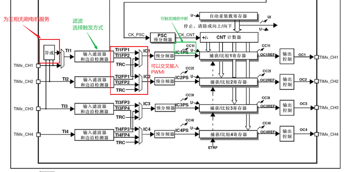
七、TIM输入捕获
IC(Input Capture)输入捕获
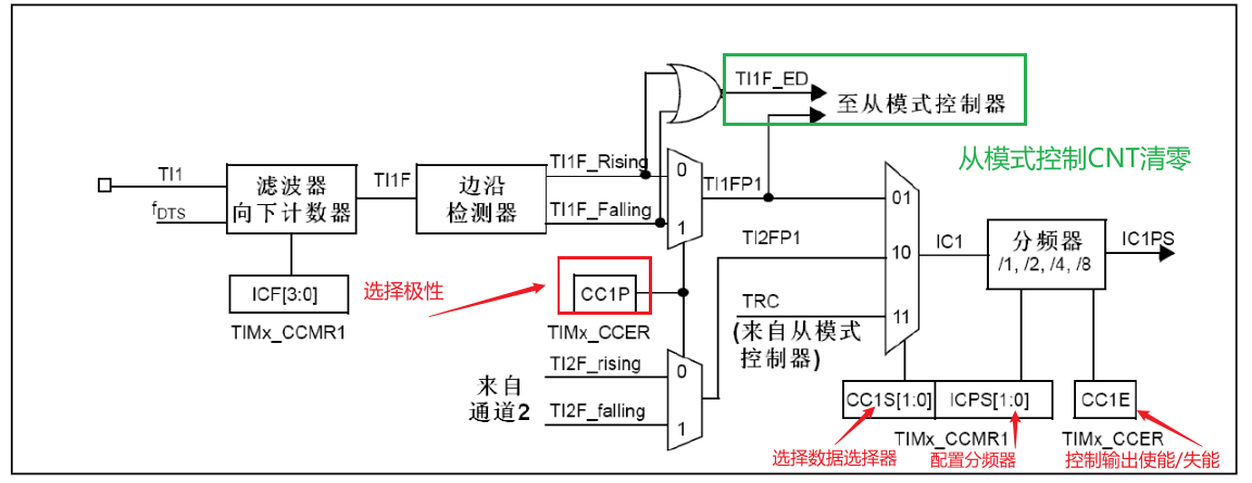
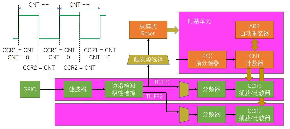
输入捕获模式下,当通道输入引脚出现指定电平跳变时,当前CNT的值将被锁存到CCR中,可用于测量PWM波形的频率、占空比、脉冲间隔、电平持续时间等参数
每个高级定时器和通用定时器都拥有4个输入捕获通道
可配置为PWMI模式,同时测量频率和占空比
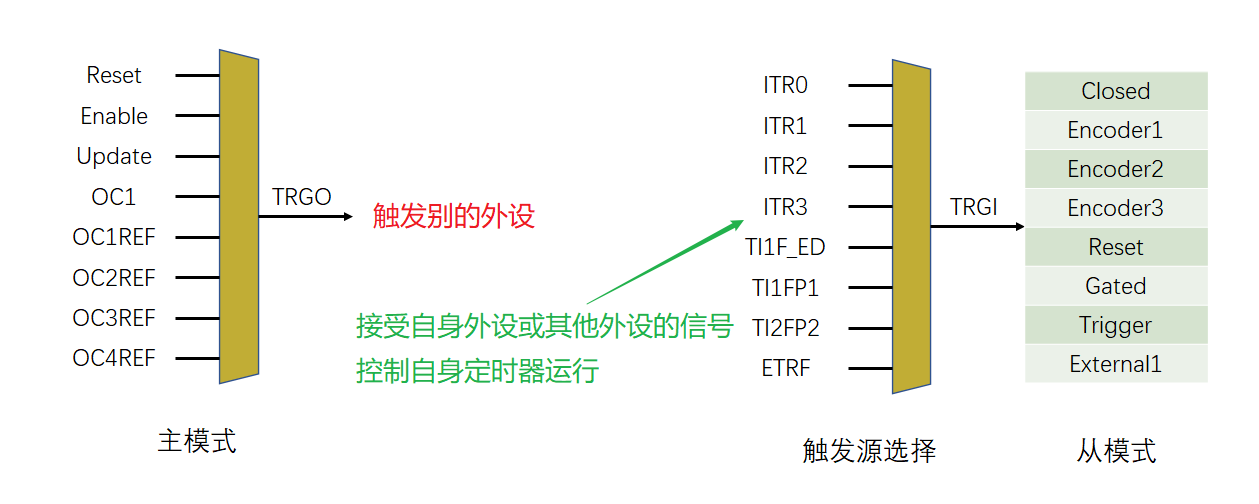
可配合主从触发模式,实现硬件全自动测量
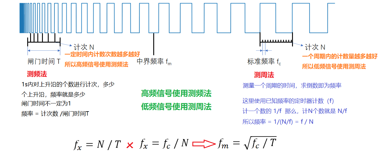
7.1频率测量
测频法:在闸门时间T内,对上升沿计次,得到N,则频率【f~x~=N / T】
测周法:两个上升沿内,以标准频率fc计次,得到N ,则频率【f~x~=f~c~/ N】
中界频率:测频法与测周法误差相等的频率点【f~m~=√(f~c~/ T)】

7.2输入捕获通道


7.3主从触发模式

7.4两种捕获方式基本结构
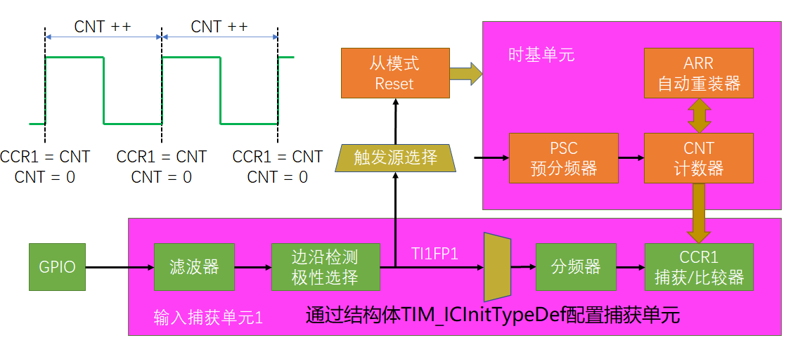
7.4.1输入捕获基本结构
触发源选择只有TI1和TI2,没有TI3和TI4,如果使用从模式自动清零CNT只能使用通道1和通道2
如果使用通道3和通道4只能开启捕获中断,手动清零

7.4.2PWMI基本结构

实例三、输入捕获模式测频率&PWMI模式测频率占空比
3.1、输入捕获模式测频率
功能实现:PA0口输出,PA6口测量
IC.c
1
2
3
4
5
6
7
8
9
10
11
12
13
14
15
16
17
18
19
20
21
22
23
24
25
26
27
28
29
30
31
32
33
34
35
36
37
38
39
40
41
42
43
44
45
46
47
48
49
50
51
52
| #include "stm32f10x.h"
void IC_Init(void)
{
RCC_APB1PeriphClockCmd(RCC_APB1Periph_TIM3,ENABLE);
RCC_APB2PeriphClockCmd(RCC_APB2Periph_GPIOA,ENABLE);
GPIO_InitTypeDef GPIO_InitStructure;
GPIO_InitStructure.GPIO_Mode = GPIO_Mode_IPU;
GPIO_InitStructure.GPIO_Pin = GPIO_Pin_6;
GPIO_InitStructure.GPIO_Speed = GPIO_Speed_50MHz;
GPIO_Init(GPIOA,&GPIO_InitStructure);
TIM_InternalClockConfig(TIM3);
TIM_TimeBaseInitTypeDef TIM_TimeBaseInitStructure;
TIM_TimeBaseInitStructure.TIM_ClockDivision = TIM_CKD_DIV1;
TIM_TimeBaseInitStructure.TIM_CounterMode = TIM_CounterMode_Up;
TIM_TimeBaseInitStructure.TIM_Period = 65536 - 1;
TIM_TimeBaseInitStructure.TIM_Prescaler = 72 - 1;
TIM_TimeBaseInitStructure.TIM_RepetitionCounter = 0;
TIM_TimeBaseInit(TIM3,&TIM_TimeBaseInitStructure);
TIM_ICInitTypeDef TIM_ICInitStructure;
TIM_ICInitStructure.TIM_Channel = TIM_Channel_1;
TIM_ICInitStructure.TIM_ICFilter = 0xF;
TIM_ICInitStructure.TIM_ICPolarity = TIM_ICPolarity_Rising;
TIM_ICInitStructure.TIM_ICPrescaler = TIM_ICPSC_DIV1;
TIM_ICInitStructure.TIM_ICSelection = TIM_ICSelection_DirectTI;
TIM_ICInit(TIM3,&TIM_ICInitStructure);
TIM_SelectInputTrigger(TIM3, TIM_TS_TI1FP1);
TIM_SelectSlaveMode(TIM3, TIM_SlaveMode_Reset);
TIM_Cmd(TIM3,ENABLE);
}
uint32_t IC_GetFreq(void)
{
return 1000000 / (TIM_GetCapture1(TIM3) + 1);
}
|
IC.h
1
2
3
4
5
6
7
| #ifndef __IC_H__
#define __IC_H__
void IC_Init(void);
uint32_t IC_GetFreq(void);
#endif
|
PWM.c
1
2
3
4
5
6
7
8
9
10
11
12
13
14
15
16
17
18
19
20
21
22
23
24
25
26
27
28
29
30
31
32
33
34
35
36
37
38
39
40
41
42
43
44
45
46
47
48
49
50
51
52
53
54
55
| #include "stm32f10x.h"
void PWM_Init(void){
RCC_APB1PeriphClockCmd(RCC_APB1Periph_TIM2,ENABLE);
RCC_APB2PeriphClockCmd(RCC_APB2Periph_GPIOA,ENABLE);
GPIO_InitTypeDef GPIO_InitStructure;
GPIO_InitStructure.GPIO_Mode = GPIO_Mode_AF_PP;
GPIO_InitStructure.GPIO_Pin = GPIO_Pin_0;
GPIO_InitStructure.GPIO_Speed = GPIO_Speed_50MHz;
GPIO_Init(GPIOA,&GPIO_InitStructure);
TIM_InternalClockConfig(TIM2);
TIM_TimeBaseInitTypeDef TIM_TimeBaseInitStructure;
TIM_TimeBaseInitStructure.TIM_ClockDivision = TIM_CKD_DIV1;
TIM_TimeBaseInitStructure.TIM_CounterMode = TIM_CounterMode_Up;
TIM_TimeBaseInitStructure.TIM_Period = 100 - 1;
TIM_TimeBaseInitStructure.TIM_Prescaler = 720 - 1;
TIM_TimeBaseInitStructure.TIM_RepetitionCounter = 0;
TIM_TimeBaseInit(TIM2,&TIM_TimeBaseInitStructure);
TIM_OCInitTypeDef TIM_OCInitStructure;
TIM_OCStructInit(&TIM_OCInitStructure);
TIM_OCInitStructure.TIM_OCMode = TIM_OCMode_PWM1;
TIM_OCInitStructure.TIM_OCPolarity = TIM_OCPolarity_High;
TIM_OCInitStructure.TIM_OutputState = TIM_OutputState_Enable;
TIM_OCInitStructure.TIM_Pulse = 0;
TIM_OC1Init(TIM2, &TIM_OCInitStructure);
TIM_Cmd(TIM2,ENABLE);
}
void PWM_SetCompare1(uint16_t Compare)
{
TIM_SetCompare1(TIM2, Compare);
}
void PWM_SetPrescaler(uint16_t Prescaler)
{
TIM_PrescalerConfig(TIM2, Prescaler, TIM_PSCReloadMode_Update);
}
|
PWM.h
1
2
3
4
5
6
7
8
9
| #ifndef __PWM_H__
#define __PWM_H__
void PWM_Init(void);
void PWM_SetCompare1(uint16_t Compare);
void PWM_SetPrescaler(uint16_t Prescaler);
#endif
|
main.c
1
2
3
4
5
6
7
8
9
10
11
12
13
14
15
16
17
18
19
20
21
22
| #include "stm32f10x.h"
#include "Delay.h"
#include "PWM.h"
#include "OLED.h"
#include "IC.h"
uint8_t i;
int main(){
OLED_Init();
PWM_Init();
IC_Init();
OLED_ShowString(1,1,"Freq:00000HZ");
PWM_SetCompare1(50);
PWM_SetPrescaler(720-1);
while(1){
OLED_ShowNum(1,6,IC_GetFreq(),5);
}
}
|
OLED.c
OLED.h
3.2、PWMI模式测量占空比
功能实现:PA0口输出,PA6口测量,双通道分别测量频率和占空比
注意:可以使用TIM_PWMIConfig函数直接配置另一个通道
IC.c
1
2
3
4
5
6
7
8
9
10
11
12
13
14
15
16
17
18
19
20
21
22
23
24
25
26
27
28
29
30
31
32
33
34
35
36
37
38
39
40
41
42
43
44
45
46
47
48
49
50
51
52
53
54
55
56
57
58
59
60
61
| #include "stm32f10x.h"
void IC_Init(void)
{
RCC_APB1PeriphClockCmd(RCC_APB1Periph_TIM3,ENABLE);
RCC_APB2PeriphClockCmd(RCC_APB2Periph_GPIOA,ENABLE);
GPIO_InitTypeDef GPIO_InitStructure;
GPIO_InitStructure.GPIO_Mode = GPIO_Mode_IPU;
GPIO_InitStructure.GPIO_Pin = GPIO_Pin_6;
GPIO_InitStructure.GPIO_Speed = GPIO_Speed_50MHz;
GPIO_Init(GPIOA,&GPIO_InitStructure);
TIM_InternalClockConfig(TIM3);
TIM_TimeBaseInitTypeDef TIM_TimeBaseInitStructure;
TIM_TimeBaseInitStructure.TIM_ClockDivision = TIM_CKD_DIV1;
TIM_TimeBaseInitStructure.TIM_CounterMode = TIM_CounterMode_Up;
TIM_TimeBaseInitStructure.TIM_Period = 65536 - 1;
TIM_TimeBaseInitStructure.TIM_Prescaler = 72 - 1;
TIM_TimeBaseInitStructure.TIM_RepetitionCounter = 0;
TIM_TimeBaseInit(TIM3,&TIM_TimeBaseInitStructure);
TIM_ICInitTypeDef TIM_ICInitStructure;
TIM_ICInitStructure.TIM_Channel = TIM_Channel_1;
TIM_ICInitStructure.TIM_ICFilter = 0xF;
TIM_ICInitStructure.TIM_ICPolarity = TIM_ICPolarity_Rising;
TIM_ICInitStructure.TIM_ICPrescaler = TIM_ICPSC_DIV1;
TIM_ICInitStructure.TIM_ICSelection = TIM_ICSelection_DirectTI;
TIM_PWMIConfig(TIM3,&TIM_ICInitStructure);
TIM_ICInit(TIM3,&TIM_ICInitStructure);
TIM_SelectInputTrigger(TIM3, TIM_TS_TI1FP1);
TIM_SelectSlaveMode(TIM3, TIM_SlaveMode_Reset);
TIM_Cmd(TIM3,ENABLE);
}
uint32_t IC_GetFreq(void)
{
return 1000000 / (TIM_GetCapture1(TIM3) + 1);
}
uint32_t IC_GetDuty(void)
{
return (TIM_GetCapture2(TIM3) + 1) * 100 / (TIM_GetCapture1(TIM3) + 1);
}
|
IC.h
1
2
3
4
5
6
7
8
| #ifndef __IC_H__
#define __IC_H__
void IC_Init(void);
uint32_t IC_GetFreq(void);
uint32_t IC_GetDuty(void);
#endif
|
PWM.c
1
2
3
4
5
6
7
8
9
10
11
12
13
14
15
16
17
18
19
20
21
22
23
24
25
26
27
28
29
30
31
32
33
34
35
36
37
38
39
40
41
42
43
44
45
46
47
48
49
50
51
52
53
54
55
| #include "stm32f10x.h"
void PWM_Init(void){
RCC_APB1PeriphClockCmd(RCC_APB1Periph_TIM2,ENABLE);
RCC_APB2PeriphClockCmd(RCC_APB2Periph_GPIOA,ENABLE);
GPIO_InitTypeDef GPIO_InitStructure;
GPIO_InitStructure.GPIO_Mode = GPIO_Mode_AF_PP;
GPIO_InitStructure.GPIO_Pin = GPIO_Pin_0;
GPIO_InitStructure.GPIO_Speed = GPIO_Speed_50MHz;
GPIO_Init(GPIOA,&GPIO_InitStructure);
TIM_InternalClockConfig(TIM2);
TIM_TimeBaseInitTypeDef TIM_TimeBaseInitStructure;
TIM_TimeBaseInitStructure.TIM_ClockDivision = TIM_CKD_DIV1;
TIM_TimeBaseInitStructure.TIM_CounterMode = TIM_CounterMode_Up;
TIM_TimeBaseInitStructure.TIM_Period = 100 - 1;
TIM_TimeBaseInitStructure.TIM_Prescaler = 720 - 1;
TIM_TimeBaseInitStructure.TIM_RepetitionCounter = 0;
TIM_TimeBaseInit(TIM2,&TIM_TimeBaseInitStructure);
TIM_OCInitTypeDef TIM_OCInitStructure;
TIM_OCStructInit(&TIM_OCInitStructure);
TIM_OCInitStructure.TIM_OCMode = TIM_OCMode_PWM1;
TIM_OCInitStructure.TIM_OCPolarity = TIM_OCPolarity_High;
TIM_OCInitStructure.TIM_OutputState = TIM_OutputState_Enable;
TIM_OCInitStructure.TIM_Pulse = 0;
TIM_OC1Init(TIM2, &TIM_OCInitStructure);
TIM_Cmd(TIM2,ENABLE);
}
void PWM_SetCompare1(uint16_t Compare)
{
TIM_SetCompare1(TIM2, Compare);
}
void PWM_SetPrescaler(uint16_t Prescaler)
{
TIM_PrescalerConfig(TIM2, Prescaler, TIM_PSCReloadMode_Update);
}
|
PWM.h
1
2
3
4
5
6
7
8
9
| #ifndef __PWM_H__
#define __PWM_H__
void PWM_Init(void);
void PWM_SetCompare1(uint16_t Compare);
void PWM_SetPrescaler(uint16_t Prescaler);
#endif
|
main.c
1
2
3
4
5
6
7
8
9
10
11
12
13
14
15
16
17
18
19
20
21
22
23
24
25
| #include "stm32f10x.h"
#include "Delay.h"
#include "PWM.h"
#include "OLED.h"
#include "IC.h"
uint8_t i;
int main(){
OLED_Init();
PWM_Init();
IC_Init();
OLED_ShowString(1,1,"Freq:00000HZ");
OLED_ShowString(2,1,"Duty:00%");
PWM_SetPrescaler(7200-1);
PWM_SetCompare1(90);
while(1){
OLED_ShowNum(1,6,IC_GetFreq(),5);
OLED_ShowNum(2,6,IC_GetDuty(),2);
}
}
|
OLED.c
OLED.h
八、TIM编码器接口
Encoder Interface 编码器接口
编码器接口可接收增量(正交)编码器的信号,根据编码器旋转产生的正交信号脉冲,自动控制CNT自增或自减,从而指示编码器的位置、旋转方向和旋转速度
每个高级定时器和通用定时器都拥有1个编码器接口
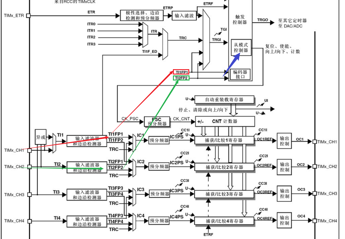
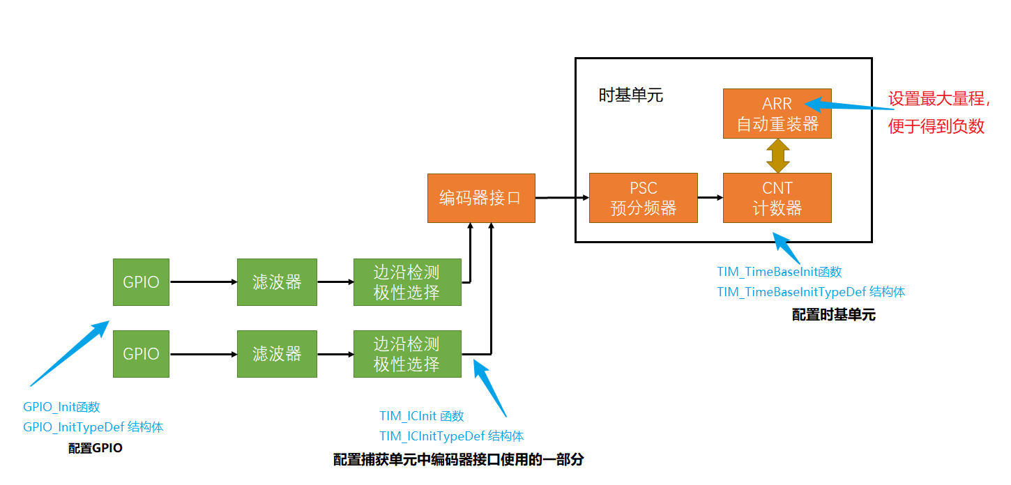
两个输入引脚借用了输入捕获的通道1和通道2
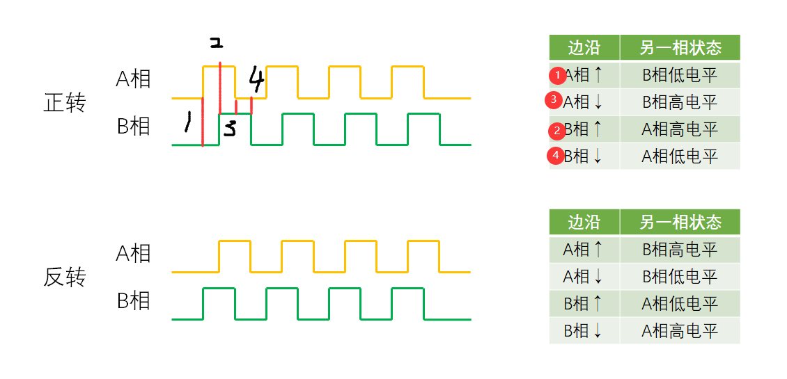
8.1正交编码器
正交信号:正转和反转的位相相差90°
正交信号的优势:精度高、可以抗噪声

8.2编码器接口基本结构
参考手册框图:

简化原理图:

8.3工作模式

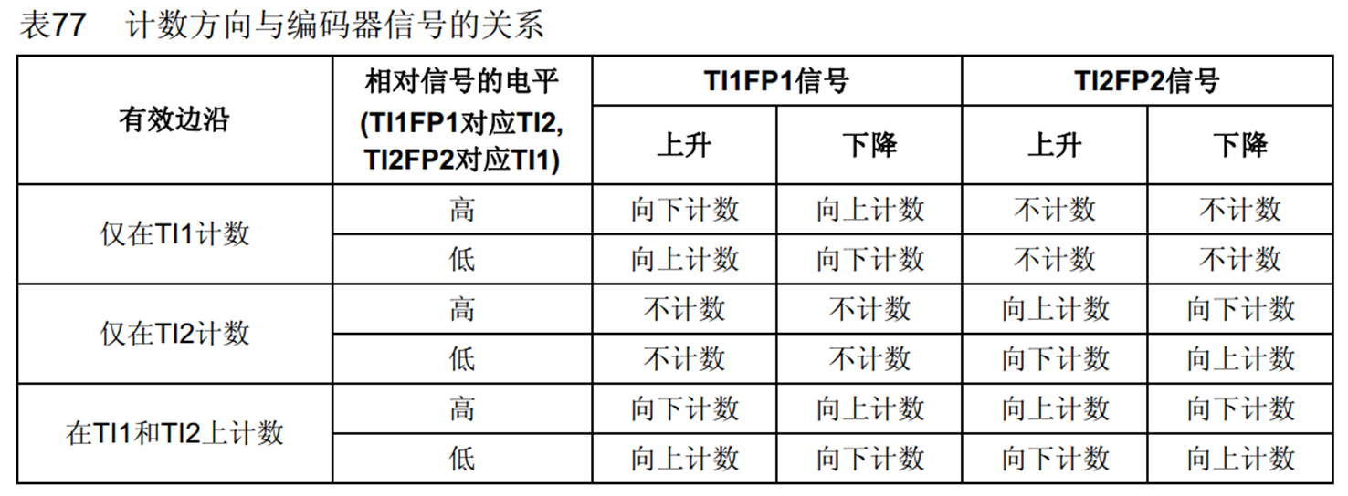
实例四编码器接口测速
Encoder.c
1
2
3
4
5
6
7
8
9
10
11
12
13
14
15
16
17
18
19
20
21
22
23
24
25
26
27
28
29
30
31
32
33
34
35
36
37
38
39
40
41
42
43
44
45
46
47
48
49
50
51
52
53
54
55
56
57
58
59
60
61
62
63
64
| #include "stm32f10x.h"
void Encoder_Init(void){
RCC_APB1PeriphClockCmd(RCC_APB1Periph_TIM3,ENABLE);
RCC_APB2PeriphClockCmd(RCC_APB2Periph_GPIOA,ENABLE);
GPIO_InitTypeDef GPIO_InitStructure;
GPIO_InitStructure.GPIO_Mode = GPIO_Mode_IPU;
GPIO_InitStructure.GPIO_Pin = GPIO_Pin_6|GPIO_Pin_7;
GPIO_InitStructure.GPIO_Speed = GPIO_Speed_50MHz;
GPIO_Init(GPIOA,&GPIO_InitStructure);
TIM_TimeBaseInitTypeDef TIM_TimeBaseInitStructure;
TIM_TimeBaseInitStructure.TIM_ClockDivision = TIM_CKD_DIV1;
TIM_TimeBaseInitStructure.TIM_CounterMode = TIM_CounterMode_Up;
TIM_TimeBaseInitStructure.TIM_Period = 65536 - 1;
TIM_TimeBaseInitStructure.TIM_Prescaler = 1 - 1;
TIM_TimeBaseInitStructure.TIM_RepetitionCounter = 0;
TIM_TimeBaseInit(TIM3,&TIM_TimeBaseInitStructure);
TIM_ICInitTypeDef TIM_ICInitStructure;
TIM_ICInitStructure.TIM_Channel = TIM_Channel_1;
TIM_ICInitStructure.TIM_ICFilter = 0xF;
TIM_ICInit(TIM3,&TIM_ICInitStructure);
TIM_ICInitStructure.TIM_Channel = TIM_Channel_1;
TIM_ICInitStructure.TIM_ICFilter = 0xF;
TIM_ICInit(TIM3,&TIM_ICInitStructure);
TIM_EncoderInterfaceConfig(TIM3,TIM_EncoderMode_TI12,TIM_ICPolarity_Rising,TIM_ICPolarity_Rising);
TIM_Cmd(TIM3,ENABLE);
}
int16_t Encoder_Get(void){
int16_t temp;
temp = TIM_GetCounter(TIM3);
TIM_SetCounter(TIM3,0);
return temp;
}
|
Encoder.h
1
2
3
4
5
6
7
8
| #ifndef __ENCODER_H__
#define __ENCODER_H__
void Encoder_Init(void);
int16_t Encoder_Get(void);
#endif
|
Timer.c
1
2
3
4
5
6
7
8
9
10
11
12
13
14
15
16
17
18
19
20
21
22
23
24
25
26
27
28
29
30
31
32
33
34
35
36
37
38
39
| #include "stm32f10x.h"
void Timer_Init(void){
RCC_APB1PeriphClockCmd(RCC_APB1Periph_TIM2,ENABLE);
TIM_InternalClockConfig(TIM2);
TIM_TimeBaseInitTypeDef TIM_TimeBaseInitStructure;
TIM_TimeBaseInitStructure.TIM_ClockDivision = TIM_CKD_DIV1;
TIM_TimeBaseInitStructure.TIM_CounterMode = TIM_CounterMode_Up;
TIM_TimeBaseInitStructure.TIM_Period = 10000 - 1;
TIM_TimeBaseInitStructure.TIM_Prescaler = 7200 - 1;
TIM_TimeBaseInitStructure.TIM_RepetitionCounter = 0;
TIM_TimeBaseInit(TIM2,&TIM_TimeBaseInitStructure);
TIM_ClearFlag(TIM2,TIM_IT_Update);
TIM_ITConfig(TIM2,TIM_IT_Update,ENABLE);
NVIC_PriorityGroupConfig(NVIC_PriorityGroup_2);
NVIC_InitTypeDef NVIC_InitStructure;
NVIC_InitStructure.NVIC_IRQChannel = TIM2_IRQn;
NVIC_InitStructure.NVIC_IRQChannelCmd = ENABLE;
NVIC_InitStructure.NVIC_IRQChannelPreemptionPriority = 2;
NVIC_InitStructure.NVIC_IRQChannelSubPriority = 1;
NVIC_Init(&NVIC_InitStructure);
TIM_Cmd(TIM2,ENABLE);
}
|
Timer.h
1
2
3
4
5
6
7
| #ifndef __TIMER_H__
#define __TIMER_H__
void Timer_Init(void);
#endif
|
main.c
1
2
3
4
5
6
7
8
9
10
11
12
13
14
15
16
17
18
19
20
21
22
23
24
25
26
27
28
| #include "stm32f10x.h"
#include "OLED.h"
#include "Timer.h"
#include "Encoder.h"
int16_t speed;
int main(){
OLED_Init();
Timer_Init();
Encoder_Init();
OLED_ShowString(1,1,"SPEED:");
while(1){
OLED_ShowSignedNum(2,1,speed,5);
}
}
void TIM2_IRQHandler(void){
if(TIM_GetITStatus(TIM2,TIM_IT_Update) == SET){
speed = Encoder_Get();
TIM_ClearITPendingBit(TIM2,TIM_IT_Update);
}
}
|
OLED.c
OLED.h
